
 EN
EN
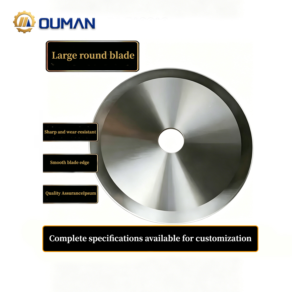
When Off‑the‑Shelf Blades Cost More Than You Think
A packaging plant in Ohio ordered what seemed like a standard replacement blade for their case‑sealing line. The price was attractive, and the delivery was prompt. Within three weeks, however, the blades were dulling twice as fast as the original OEM parts. Production slowed, scrap rates climbed by 12%, and the maintenance team was swapping blades every shift instead of weekly. The problem wasn't the steel grade on the spec sheet—it was the geometry. The edge angle, though close to the original, was just one degree off, causing the blade to drag rather than slice cleanly.
This experience is far from unique. Over the past six years, our manufacturing team has partnered with over 80 industrial clients—from food processors to recycling facilities—to produce custom blades that solve real operational problems. The single most common source of frustration we encounter is not poor steel quality, but mismatched specifications that could have been caught early in the ordering process. Understanding the custom blade procurement journey isn't just procurement knowledge; it is a practical skill that directly impacts production uptime, product quality, and operational costs.
From Inquiry to CAD Approval – Aligning Specifications with Manufacturing Reality
The ordering process begins with a detailed inquiry, where the buyer defines the application, material type, and critical dimensions. Submitting a technical specification sheet or sample drawing enables the engineering team to assess production feasibility. Within 3–5 business days, a preliminary CAD model is drafted—translating raw requirements into a manufacturable geometry. During this stage, parameters like tooth pitch, bevel angle, and mounting hole patterns are validated against the selected steel grade and heat‑treatment capabilities.
A collaborative design review follows to ensure edge geometry and thickness align with the intended cutting load—preventing premature wear or breakage. Adjustments are made iteratively until both parties sign off on the final CAD, locking in tolerances and material costs. This alignment phase typically spans 1–2 weeks and significantly reduces the risk of costly rework later in production. One client in the timber industry saved over $15,000 in avoided downtime simply by catching a mounting hole misalignment during this CAD review stage—before any steel was cut.
Prototyping and Sample Validation – Testing Before Full Production
Once the CAD is approved, a prototype batch is produced using the exact manufacturing process planned for full‑scale runs. Sample validation involves rigorous testing under real‑world conditions—measuring cut quality, wear rate, and dimensional stability. For high‑volume orders, leading providers typically produce 5–10 sample pieces and share inspection reports, including hardness values (HRC) and micrographic edge analysis.
If deviations are found, the design or heat‑treatment cycle is corrected before final release. After client approval, the full production order is released, with typical lead times of 4–6 weeks for standard custom blades and 6–10 weeks for complex industrial profiles. This stage serves as a critical gate—confirming that the blades will perform as expected without compromising downstream operations. A food processing client in Texas, for example, validated their prototype blades on a pilot line for 72 hours of continuous operation before approving full production, catching a minor edge chipping issue that was corrected by adjusting the tempering temperature by 15°C.
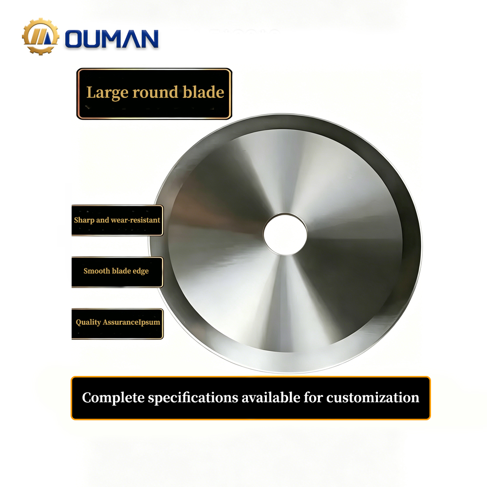
Critical Parameters – What to Specify for Your Application
Geometry, Edge Finish, and Application‑Specific Design
Cutting performance hinges on geometry and edge finish tailored to the material being processed. For timber, a chisel‑grind bevel with a polished edge minimises tearing and friction. Serrated edges excel in recycling lines where mixed contaminants demand aggressive, non‑clog cutting. In metalworking, a robust double‑bevel geometry with a micro‑honed edge resists chipping under high shear forces. Plastic sheets require a razor‑sharp, fine‑ground edge to prevent melting or burr formation—and a low‑angle bevel helps maintain clean cuts. Surface coatings such as TiN or CrN extend edge life by reducing adhesive wear. Choosing the wrong profile—for example, a straight edge for abrasive recycled materials—can increase blade change frequency by 30–50%, according to 2025 industry data. Each application demands a precise balance of rake angle, clearance, and edge radius to optimise sharpness and durability.
Material Selection – Steel Grade, Thickness, and Wear Resistance
Material choice governs hardness, toughness, and corrosion resistance. The table below summarises the trade‑offs.
| Steel Grade | Hardness (HRC) | Best Application | Key Trade‑off |
|---|---|---|---|
| SK5 (High‑Carbon Tool Steel) | 58–62 | Wood, paper, general cutting | Excellent edge retention; lower corrosion resistance |
| AISI 440C (Stainless) | 56–58 | Food processing, moist environments | Good corrosion resistance; moderate toughness |
| Tungsten Carbide / HSS | 62–68 | Recycling, metal slitting, abrasives | Extreme wear resistance; more brittle |
Blade thickness must match the cutting load: thin gauges (0.5–1.0 mm) reduce kerf loss in delicate operations, while thicker plates (2–5 mm) withstand higher impact. Critically, hardness and toughness must be balanced—a blade hardened to HRC 64 may cut longer but risks fracturing under shock loads. Thoughtful material selection ensures resilience against both abrasive wear and mechanical stress, lowering total lifecycle costs.
Precision Requirements – Tolerances, HRC Testing, and ISO 9001 QA
Strict dimensional tolerances are essential for seamless integration into automated machinery. Flatness deviations exceeding 0.05 mm across the blade length can cause uneven cutting force and accelerate wear. Hole placement tolerances of ±0.1 mm ensure proper mounting and alignment, minimising vibration. Hardness testing via Rockwell C (HRC) must be verified at multiple points: a variance greater than ±2 HRC indicates inconsistent heat treatment and increases failure risk.
| Specification | Tolerance Requirement | Validation Method |
|---|---|---|
| Flatness | ≤0.05 mm over full length | Precision straight edge / CMM |
| Hole Position | ±0.1 mm | Coordinate measuring machine |
| HRC Hardness | ±2 HRC max variation | Multi‑point Rockwell testing (ASTM E18) |
| Edge Finish | Ra ≤0.4 µm for precision cuts | Surface profilometer |
ISO 9001–certified manufacturers implement statistical process control to maintain these parameters and routinely supply inspection reports with each batch. For high‑speed packaging lines, even a 0.025 mm thickness variation can raise scrap rates. By specifying clear tolerance bands and requiring HRC test certificates, procurement teams validate that blades meet demanding production standards—and deliver consistent, predictable tool life.
Manufacturer Collaboration Models – Finding the Right Fit
OEM Drawing Replication vs. Reverse Engineering
When an existing OEM drawing is available, the manufacturer replicates the blade geometry precisely—verifying dimensions, tolerances, and edge finishes against the CAD model. If no drawing exists, reverse engineering from a physical sample becomes necessary. This process typically involves 3D scanning to capture the worn or intact blade's profile, followed by CAD modeling to restore original design intent. A prototype is then produced for dimensional validation and on‑machine testing, ensuring performance parity with the OEM part.
Client‑Driven Design Support – From Concept to Blueprint
For clients lacking formal engineering documents, a collaborative design approach transforms a rough concept sketch or application description into a manufacturable blueprint. The engineering team guides material selection, geometry optimisation, and tolerance definition based on the intended cutting medium and machine interface. This stage includes iterative CAD reviews and, when needed, functional prototyping for field testing. The goal is to refine the design until it meets both performance and cost targets—bridging the gap between a napkin sketch and a validated, production‑ready specification.
| Collaboration Model | Best For | Typical Timeline | Key Deliverable |
|---|---|---|---|
| OEM Drawing Replication | Existing design with complete documentation | 4–6 weeks | Dimensionally verified production blades |
| Reverse Engineering | No drawings; worn sample available | 6–8 weeks | Restored original geometry + CAD |
| Client‑Driven Design Support | New application; concept only | 8–12 weeks | Custom geometry with performance testing |
Selecting a Reliable Manufacturing Partner
Choosing a dependable partner directly impacts production uptime and cutting consistency. Begin by verifying ISO 9001 certification—it signals commitment to repeatable processes and tight tolerances. Assess engineering depth: top‑tier suppliers offer in‑house design support and material expertise, ensuring blade geometry matches your application, whether for timber, metal, or plastic processing. Prioritise partners with documented case studies in your industry and proven capability in OEM drawing replication or reverse engineering from samples.
Transparent communication around lead times, minimum order quantities, and after‑sales support is non‑negotiable. Confirm that hardness testing reports (HRC) and dimensional inspection data accompany every shipment. This data‑driven approach mitigates risks of premature wear, edge failure, or unplanned downtime. Ultimately, a reliable manufacturer functions as a strategic ally—helping you optimise edge life and lower total cost of ownership through collaborative design and rigorous quality assurance routines.
Engineering Partnership – What G‑Honor Games Brings to the Table
Achieving consistent blade performance requires more than processing an order—it demands a partnership with a manufacturer that controls every stage from material sourcing to final heat treatment. G‑Honor Games brings this engineering‑first philosophy to custom industrial blade production. Our facilities implement controlled‑atmosphere austenitising, precision quenching systems, and tempering protocols validated by third‑party HRC testing. We offer customised hardness ranges tailored to specific cutting applications and support both OEM replication and client‑driven design projects. Our integrated supply chain ensures consistent material sourcing and documented traceability for every batch. For industrial operators, this translates to predictable blade life, lower replacement costs, and a measurable return on investment that extends well beyond the initial purchase.
FAQ
Q: What is the typical lead time for custom industrial blades?
A: Standard custom blades typically require 4–6 weeks, while complex profiles can take 6–10 weeks, depending on geometry and tooling requirements.
Q: Why is material selection so important for industrial blades?
A: Material choice governs hardness, toughness, and corrosion resistance, ensuring optimal cutting efficiency and durability for specific applications.
Q: How is blade quality validated during prototyping?
A: Validation includes real‑world testing, inspection reports on hardness values (HRC), and micrographic edge analysis. Deviations prompt design or process corrections.
Q: How do ISO certifications impact blade production?
A: ISO 9001 ensures repeatable processes, tight tolerances, and statistical control, minimising production risks and ensuring consistent quality.
Q: What is reverse engineering, and when is it used?
A: Reverse engineering captures a blade's profile using 3D scanning to restore design intent, typically used when OEM drawings are unavailable.
Q: What factors should buyers consider when selecting a manufacturer?
A: Verify ISO certifications, assess engineering expertise, request case studies, and ensure transparent communication about lead times and QA practices.